opening

Regular reports of my grabber activity and that of others, plus information on QRSS software, hardware and technique that comes my way

Saturday, August 22, 2015

Precision Markers at Any Frequency Using an OCXO with Spectrum Lab

I recently purchased an Oven Controlled Crystal Oscillator (OCXO) on eBay to use as a "house frequency standard."  It features an SC cut crystal with a double oven and a sine wave output at 10 MHz.  The question is, how to use it on all frequencies covered by my TS-440?

I calibrated the OCXO by comparison to WWV to an accuracy of just better than 1 Hz and verified by repeated observations that it is virtually drift-free, at least for QRSS work.  I'll describe how to do this in my next post.

In the old days of tube receivers a standard method for finding the band edge was to use a 100 kHz crystal oscillator with a harmonic generator to provide markers every 100 kHz.  This posts describes a similar approach to allow the 10 MHz oscillator to provide markers every 2.44 kHz with an accuracy of 1 Hz up through the Ten Meter Band.  It couples the OCXO with a binary divider to divide down to 2.44 kHz, or 2.4414060 to be exact, then produces harmonics which occur at this interval up through 10m.

Several years ago I purchased a frequency calibrator kit from W8DIZ which used this scheme with a TCXO and a 74HC4040 12 bit Binary Counter which can be configured to divide by up to 4096.  The DIZ kit used only the divide-by 2, 4 and 8 to produce strong markers at 10, 5 and 2.5 MHz but I reconfigured it for the 4096 maximum and was pleasantly surprised to see a plethora of harmonics throughout the HF spectrum.
Figure 1.  W8DIZ Frequency Standard
The next step was to see if the sine wave output of the OCXO would do the same since Binary Counters are designed to work with square waves....and it does.  I suspect the strong output of the OCXO overdrives the 4040 counter and acts like a square wave due to clipping.  The output of the OCXO was injected directly into the DIZ circuit at the base of Q2.   To select the 4096 divide-by I scratched through the trace from pin 7 of the divider and jumpered over from pin 1.  As a sidenote, this method surpressed the output of the TCXO but by adding a gimmick capacitor between the OCXO and Q2 to reduce it's amplitude I can also see harmonics from both sources.

The output from J2 was injected into the receiver's input through a BNC "T" adapter with a gimmick capacitor to adjust the amplitude.

The difficulty of having 2.44 kHz harmonics is that they are not likely to be close enough to the frequency span of a waterfall grabber to be seen.  Consider a typical grabber screen on 30m which extends from 10130.9 to 10140.1 kHz.  The nearest marker from the OCXO is at 10139.159 kHz or about 740 Hz below the grabber window.  What to do?

Spectrum Lab is a bottomless pit of useful features along with a tiny programming language to make them work.  One of these features is an internal audio oscillator by which the frequency can be set either manually or under computer control.  The programming command to set the frequency is,

      generator[0].freq = "desired frequency",

[0] refers to the first of three oscillators and note that "desired frequency" can be an algebraic expression.

There is also a special command to measure the peak frequency of a signal in a specified interval,

     peak_f(f1,f2).

Putting it all together,

      generator[0].freq = 879 + peak_f(450,470).

I use the "Conditional Actions" section to execute the command every 1000 milliseconds.  Use "always" as the "if" statement and the generator command as the "then" statement.

The OCXO harmonic appears at an audio frequency of about 461 Hz and the second part of the above equation measures it's exact value, after which 878 is added to move the audio oscillator output frequency to a nominal value of  1340 Hz which is well within the grabber window.  I used 879 just to illustrate how to move the OCXO signal but other values could be used to move it, for example, to be close to a signal being studied.

You can familiarize yourself with the Spectrum Lab commands by clicking on the help screen and scrolling down to  Interpreter : -commands, -functions, -expressions.

Make sure your receiver's bandpass is wide enough to allow the marker frequency as well as the grabber window.

Here's an example:


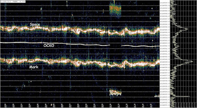
This is a high resolution study of WA5DJJ's GPS stabilized fsk QRSS signal.  The individual dots and dashes are not evident because the scan speed is very slow.  Note that the frequency range is only 20 Hz.  The slow drift of the OCXO is due to temperature changes in the receiver and can be used to correct the frequency of the signal being measured by subtraction, ie, the OCXO is the baseline.

Near the right side you can see a gap in the OCXO signal.  This was caused by QRM down at the frequency of the OCXO marker, probably from JT65.

Though this post describes precision frequency measurement for QRSS work it can be used for other applications by choosing the appropriate Spectrum Lab parameters.
Sunday, June 7, 2015

Time-sharing a Grabber for Multiband Coverage

The most popular band for QRSS work is by far 30m.  Although at least one grabber op, G0XXX, has several receivers to allow other bands to be covered most of us cover other bands by moving on special occasions, such as a "weekend on 40m" or such.  Here I describe a technique I am now using which allows me to grab on several bands by time-sharing, i.e.,  moving the grabber periodically in ten minute frames.

The best and easiest way to control a receiver's frequency is via commands sent from the computer's serial port. Unfortunately the RS232 function in my TS440 no longer works so I've devised a technique which utilizes the UP/DOWN pins on the mic jack.  On the 440, shorting pin 3 will cause the frequency or memory to increment up while shorting pin 4 moves it down.  Computer commands can be obtained from the RS234 port by sending a binary number to the COM1 address from a simple program, which in my case is FreeBasic.  Here's an example of the FreeBasic code to make that happen:

     open "COM1:9600,N,8,1,CS,DS,RS" FOR Binary AS #1
     Out &h3fc,01      Rem set DTR low
     Sleep 250,0         Rem delay 250 ms
     Out &h3fc,00      Rem Set DTR hi

&h3fc is the address of the serial port,  01 causes the DTR pin to go from -10 to +10 vdc and 00 moves it back to -10v.  The  200ms delay gives enough time for the hardware to respond but not so much that memory moves more than one channel.  02 sets the RTS hi (mic/dwn)

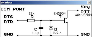
The RS232 voltages need to be converted to an open/short condition with a level converter.  This is the circuit I use (two needed) :

Circuit from QRS by ON7YD

At present I use just three bands, 40m, 30m and 20m, with 40m being replaced by 10m or 15m during the daylight hours.  Here is the program written in the QuickBasic dialect of FreeBasic:

----------------------------------------------------------------------------------------
#Lang "qb"

Dim m As Integer
OPEN  "COM1:9600,N,8,1,CS,DS,RS" FOR Binary AS #1
Out &h3fc,00
m=Val(Mid$(Time$,4,1))


Print "start"
zero: Rem inc To Next frequency when m changes (10 minutes)

If m=Val(Mid$(Time$,4,1)) Then GoTo zero
GoSub inc

Rem Print "at one"
one:  Rem inc To Next frequency when m changes (10 minutes)

If m=Val(Mid$(Time$,4,1)) Then GoTo one
GoSub inc

Rem Print "at two"
two:  Rem dec back To first frequency

If m=Val(Mid$(Time$,4,1)) Then GoTo two
GoSub dec

inc:
Print "inc"
Out &h3fc,01 Rem set DTR low
Sleep 200,0  Rem delay 250 ms
Out &h3fc,00 Rem Set DTR hi
m=Val(Mid$(Time$,4,1)) Rem set New m
Rem Print "leaving inc"

Return


dec:
Print "dec"
Out &h3fc,02 rem dec twice To Return To start frequency
Sleep 200,0
Out &h3fc,00
Sleep 1
Out &h3fc,02
Sleep 200,0
Out &h3fc,00
m=Val(Mid$(Time$,4,1))
rem Print "leaving dec"

GoTo zero

-----------------------------------------------------------------------------------------------
The program starts on the first frequency and checks the tens digit of minutes until it changes and increments to the second frequency. Repeats this a second time to reach the third frequency and finally decrements twice to return to the first frequency.  The "print" commands are for debugging.

In order to make the Spectrum Lab frequency scale show the correct values it's necessary to use the "Conditional Actions" feature to load in the "frequency offset" based on each ten minute period.  Here's what that looks like:


Be sure that the "sync" box is checked to activate "conditional actions"..

The start times of the first frequency are xx00 and xx30. The program can be started anytime during these time intervals in order to be synchronized.

Here's the steps to starting the program to ensure synchronization:

1.   Load the frequencies into the receiver's memory bank in sequential order and set to the first frequency.         The frequencies are the same as those specified in WSPR.

2.   Set up the "conditional actions" per figure xx and check the box in the files menu.

3.   Start the program between the first ten minutes (xx00 to xx10z) or the fourth ten minutes (xx30 to xx40z)       ensure synchronization.

I have chosen to use just 3 frequencies to allow each to be covered twice in one hour because it's a good compromise between bands and time between grabs for each band. At present 40/30/20m are covered at night and 15/30/20 during the day.  Changing from 40 to 15m for the first slot only requires entering the new frequency into memory slot one for the receiver and changing the corresponding frequency in the "conditional actions" table.

After debugging the software the only problem I've had is getting the delay correct in the inc: and dec: subroutines.  Remember, if the mic up/dwn button is held down the memory will scan until released and we want just one jog so it needs to be short enough to prevent this.  At the same time, if it is too brief the hardware does not have enough time to react.  For your system you may have to play with the delay.

Reference:   http://www.freebasic.net/